| ˇ@ | The Layout of the Ozonated Water System | |
| ˇ@ |
ˇ@ ˇ@ |
|
| ˇ@ |
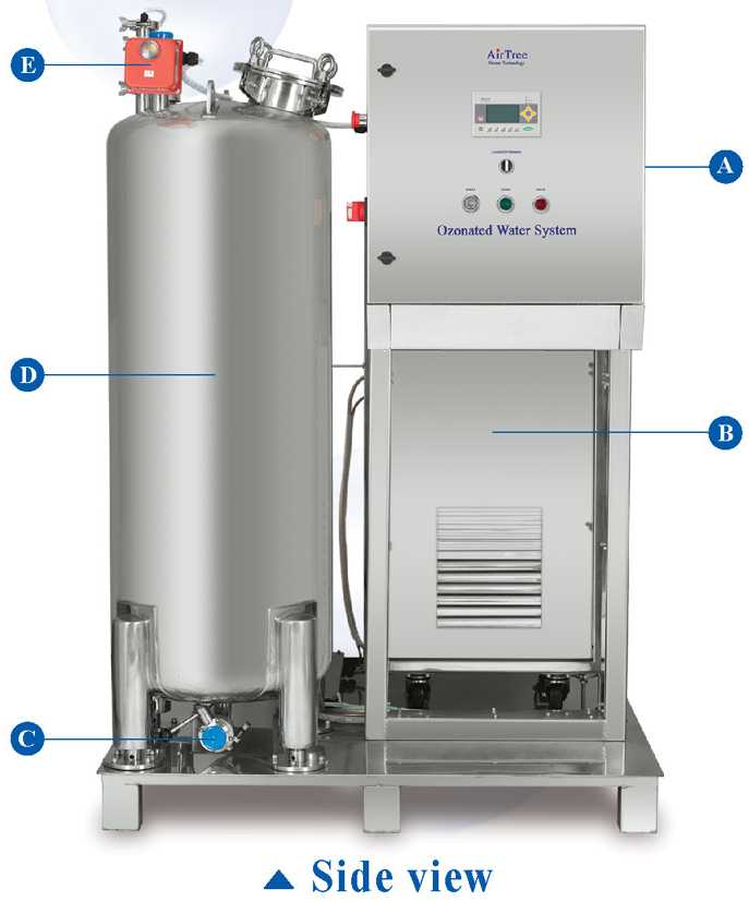
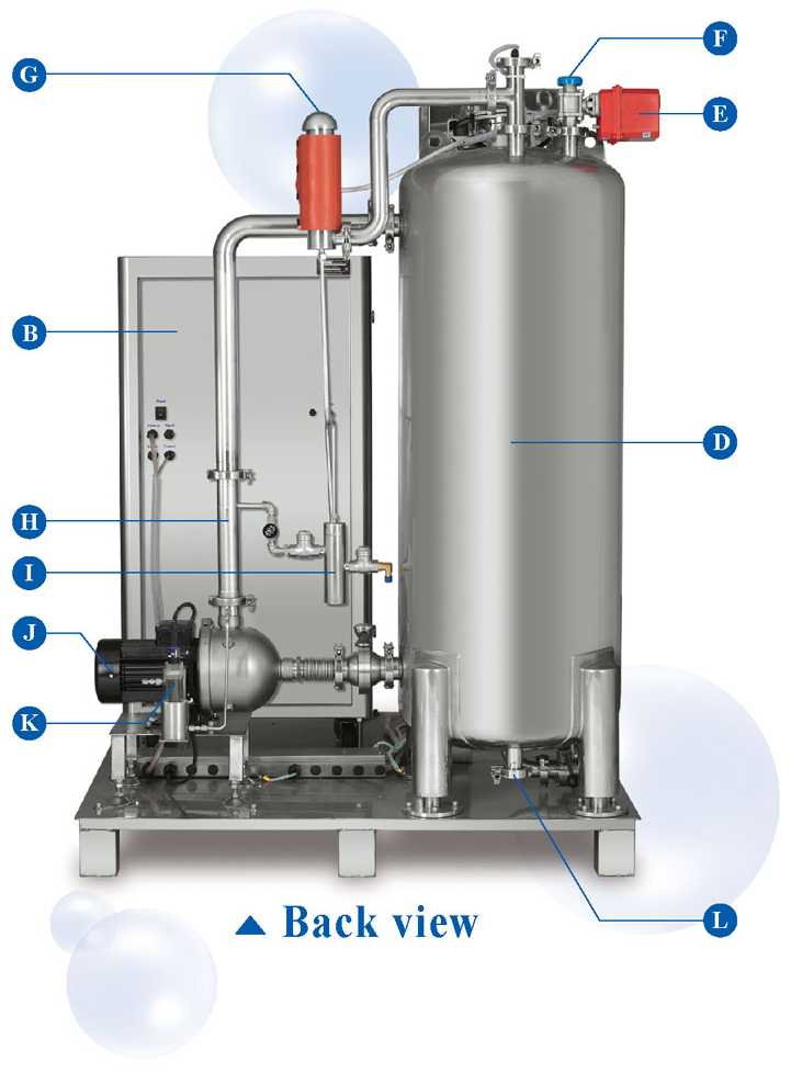
A. Control panel B. Ozone generator C. Ozonated water outlet D. Water buffer tank E. EM valve (for make up water control) F. Water inlet |
G. Ozone destructor H. CO-mixer I. Back stream leaking valve J. Booster pump K. Ozone sensor L. Drain |
| ˇ@ | ˇ@ ˇ@ ˇ@ |
|
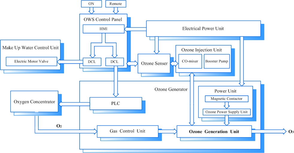
| ˇ@ | Block
Diagram ˇ@ |
|
| ˇ@ |
|
|
| ˇ@ | ˇ@ ˇ@ |
|
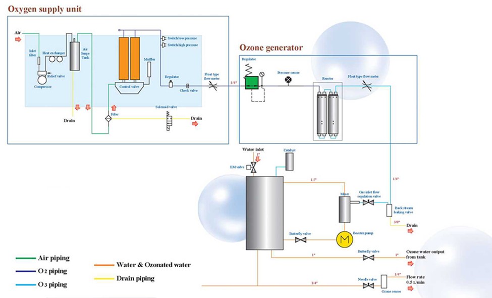
| ˇ@ | Piping
diagram ˇ@ |
|
| ˇ@ |
|
|